
Autonomous navigation and human-robot interaction, integrated. Built first for humanoids, designed to run across other robot platforms.

Humanoid robots such as those from Unitree and AGIBOT have become affordable. However, simply purchasing one of these robots does not mean it can autonomously perform useful work. While dancing and kung fu demonstrations are entertaining, the existing conversation and navigation functions that come with these robots have significant limitations for practical use.
Omakase OS is an operating system that enables such humanoid robots to become genuinely useful in environments where people are present. Rather than depending on a single OEM, it can be deployed across robots provided by a variety of different OEMs.
Human-like Multimodal Conversation
The first capability we tackled was enabling robots to communicate in a human-like manner. Offline communication in environments where people are present is far more difficult than it appears. There are many factors that must be considered, such as multiple people speaking to the robot simultaneously, how the robot should enter a conversation, whose voice it should focus on, and how it should ignore surrounding noise.
Although speech AI has advanced remarkably in recent years, it is still not the case that simply using existing AI models or APIs will make robot conversations work effectively. In the case of robots, they must be able to converse while observing their surroundings, and achieving this kind of multimodal conversation without introducing latency is a major challenge. We developed our own proprietary conversation engine that runs on our own GPUs. Furthermore, by learning the voice of any individual, this conversation engine enables the robot to communicate as though it were that person.
What Should Be Optimized?
When discussing conversational speed, many implementations measure “the time until a response is returned.” However, for face-to-face robots, what matters is not when the response has finished being generated, but when the robot begins speaking. People judge that they have been heard the moment the other party starts talking, and from that point onward, the remaining duration has little effect on how natural the conversation feels. For this reason, we use the time between the end of the user’s speech and the first audio produced by the robot—time-to-first-audio (TTFA)—as our primary design metric.
With batch processing, TTFA cannot be reduced until the entire response has been generated.
TTFA_batch = T_speech recognition + T_generation(y) + T_speech synthesis(y)
Here, y represents the complete response text. Our implementation streams the language model’s output by splitting it at punctuation boundaries and begins speech synthesis as soon as the first segment, s₁, has been completed. Regardless of how many sentences the response contains, TTFA only waits for this first segment.
TTFA_streaming = T_speech recognition + T_first token + T_generation(s₁) + T_speech synthesis(s₁)
Furthermore, for only the first segment, we reduce the number of synthesis refinement iterations, while prioritizing audio quality from the second segment onward. We therefore treat the speed at which speech begins and the quality of speech after it has begun as two independent parameters that can be optimized separately.
Table 1. Response Timing with Streaming Processing
Comparison with and without a camera image. The image was captured at 640 × 480, JPEG quality 80, matching the robot’s head camera configuration.
The clearest result was that adding a single image increased processing time by almost nothing. The difference in TTFA was only 3 ms, which is small enough to fall within normal measurement variation. The visual tokens are absorbed during preprocessing before generation begins, meaning this stage is not the bottleneck. As a result, allowing the robot to observe its surroundings while speaking comes with virtually no performance penalty. Confirming that there is no computational reason to sacrifice “seeing while speaking” became the basis for enabling this capability by default.

Figure 1. Time Breakdown of a Single Conversation Turn
(Measured on August 4, 2026; median values.) The top two rows compare batch processing and streaming processing for the same pipeline. With streaming, the robot begins speaking before the entire response has been generated. The third row shows the same process with one camera image added, where the difference is negligible. The bottom row shows the same server accessed over a wide-area network, where the additional 1.42 seconds is entirely due to network latency rather than computation. The dashed line indicates 0.7 seconds, the point at which humans are generally considered to begin perceiving conversational delay.
Another experiment placed the same processing pipeline on a remote GPU. When the same audio was transmitted over a network with a 120 ms round-trip latency, TTFA increased from 1.18 seconds to 2.60 seconds. The additional 1.42 seconds contained not a single millisecond of computation—it was entirely the result of transmitting the audio data back and forth over the network. The single most effective way to reduce conversational latency was therefore not model selection or quantization, but placing the GPU in the same location as the robot. This is one of the primary reasons why we host our conversation engine ourselves. The other is that conversations continue uninterrupted even if the network connection is lost.
That said, a TTFA of 1.18 seconds still exceeds the 0.7-second threshold at which people begin to perceive delay. The next opportunity for improvement lies in speech recognition. At present, recognition begins only after the user has finished speaking. By switching to a streaming speech recognition architecture that operates while the user is still speaking, most of the recognition time can be hidden behind the duration of the utterance itself.
Voice Learning
The conversation engine can learn the voice of a specific individual, allowing the robot to speak as though it were that person. The underlying speech synthesis model remains unchanged, while only the voice-specific differences are learned as a small adapter.

Figure 2. What’s Required to Add One Voice
Actual training results from a voice currently used in production. Recording: 6 minutes. Training: approximately 5 minutes. Output: 84 MB. The base model is shared, and only the voice-specific adapter is replaced.
Table 2. Voice Training Results (One Production Speaker)
Expressed numerically, the cost of adding a new voice is simply a 6-minute recording session and 5 minutes of training. Since the voice exists as a file rather than becoming part of the model itself, the same voice can be deployed across any robot, while different voices can also be assigned to different deployment sites.
The next capability we developed after conversation was autonomous navigation. The ability for a robot to move around autonomously is one of its most fundamental functions. Rather than adopting an end-to-end approach such as Vision Language Navigation (VLN), we implemented a SLAM-based navigation system using 3D LiDAR.
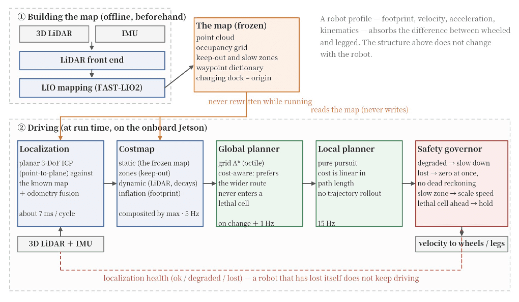
Figure 3. Navigation Architecture
The key design principle is the complete separation of the mapping phase from the navigation phase. During navigation, the map is never modified. Localization consists solely of matching against a previously generated map, and the reliability of that localization governs every downstream velocity command. Differences between individual robots are encapsulated within a single profile, allowing the overall architecture to remain identical regardless of whether the robot is wheeled or legged.
To briefly explain the safety-related aspects, the most important component of this architecture is not the path planner, but the safety governor. If localization quality is judged to be degraded, a scaling factor is applied to the robot’s velocity. If localization is lost, all velocity commands are immediately reduced to zero. We deliberately do not allow the robot to continue operating using dead reckoning alone. A robot that loses track of its position and continues moving without realizing it has become lost is one of the most dangerous failure modes in a real-world deployment.
Validation at the University of Tsukuba Hospital
In March 2026, we conducted a proof-of-concept trial at the University of Tsukuba Hospital, evaluating nighttime patrols and multilingual guidance services. During this trial, we primarily evaluated the robot’s conversation and navigation capabilities, confirming use cases in which a bipedal robot navigated around obstacles to guide people to their destinations and perform nighttime patrols within an actual hospital environment. Testing autonomous navigation in a feature-sparse environment such as a hospital proved to be particularly valuable.
Table 3. First Field Trial (March 23–25, 2026)
First-floor lobby, bipedal robot. Travel distance and patrol time include only valid autonomous runs during which localization remained stable.
37
910 m
70.6 mins
169
52
297
90.8 %
82.2 %
92.3 %
86.2 %
64.4 %
94.9 %
78.8 %
82.0 %
0 / 0
0 / 0
0 / 0
0 / 0
Across the three-day trial, the robot recorded zero falls, zero collisions, 910 meters of autonomous travel, and an 86.2% waypoint arrival rate. The robot’s movement itself performed as expected. At the same time, the trial clearly exposed a weakness. Relocalization—either when recovering the robot after startup or after localization had been lost—was not sufficiently stable, and during longer navigation sessions, some runs accumulated increasing localization error over time. The hospital lobby, with its lack of distinctive visual features, proved to be an environment in which this weakness was particularly apparent.
In June 2026, we returned to the same hospital for a second proof-of-concept trial to evaluate additional capabilities. During this second trial, we tested robots from different vendors and evaluated navigation over longer travel distances.
Table 4. Second Field Trial (June 24–25, 2026, 19:00–21:00 each day, First Floor)
Travel distance by robot (in meters).
1,338
1,343
2,681
The total travel distance during the second trial reached 2,681 meters, approximately three times greater than during the first trial. While autonomous navigation was successfully evaluated on the quadruped robot, the wheeled robot did not achieve the desired level of autonomous navigation during this trial, and guided navigation was instead performed through teleoperation.
The reason we have described these results in such detail is that the weaknesses uncovered during field trials directly determined the next iteration of our system design. Had we not encountered the instability of relocalization during the first trial, we would never have identified the underlying structural limitations of our navigation architecture. For us, deploying robots in real environments has become the most effective method of designing better systems.
Table 5. Measured Results in Simulation with the Current Architecture
12 × 8 m indoor environment with no-entry zones, slow-speed zones, and moving obstacles. Validation on physical robots is planned.
0.30 m/s / 0.63 m/s
Minimum distance to moving obstacle
2.16 m
Response after injected localization loss
Velocity commands reduced to zero in approximately 0.04 seconds, then successfully recovered and reached the goal
Robust navigation requires both a reliable evaluation framework and validation in real-world environments. We continue improving our system through practical deployment and iterative refinement in the field.
Proprietary Real-Time Action Recognition Model
As we continued validating Omakase OS across a variety of real-world environments, the robot’s reaction speed became a major challenge. When someone waves and approaches the robot, it needs to respond almost in real time. Likewise, if someone extends their hand for a handshake, the robot should naturally respond by shaking hands. To address this, we developed our own deep learning-based action recognition model.
This problem has three constraints that distinguish it from conventional action recognition research: latency (a correct answer is meaningless if it arrives too late), computational resources (the model must run on the Jetson embedded in the robot rather than on a training GPU), and interpretability (if we cannot understand why the model makes mistakes, we cannot improve it). We evaluated skeletal representations and model architectures side by side while considering all three constraints simultaneously.

Figure 4. Action Recognition Pipeline
Skeleton data is extracted from the head-mounted RGB-D camera, the nearest person is selected from among multiple individuals, and a sequence of 10 frames (1 second) is classified into one of five action classes. In addition to wrist joints, points on the torso and face are also included because gaze direction is a strong indicator of whether someone is trying to interact with the robot.
Collecting and annotating diverse Human-Robot Interaction (HRI) datasets is extremely expensive. Rather than relying solely on additional real-world data collection, we adopted a strategy of explicitly modeling and augmenting the key sources of variation. By geometrically synthesizing three factors—the person’s dominant hand, movement speed, and changes in camera pose caused by movement of the robot’s head—we increased the size of the dataset by approximately 12×. However, the effectiveness of this augmentation depended on the conditions, and variation between different people could not be compensated for through augmentation alone. No matter how much data we generated from a single individual, the resulting model never matched the performance of one trained using data collected from multiple people.
Accuracy and Real-Time Performance Are Not the Same
We compared 14 spatio-temporal feature extraction models side by side. Classification accuracy alone is not sufficient as an evaluation metric. What matters in practice is the time between the start of a person’s movement and the point at which the robot correctly recognizes it. Once this exceeds 0.7 seconds, people begin to perceive the response as delayed. In other words, even if a classifier is highly accurate, if inference on the Jetson takes 600 ms, nearly the entire response budget has already been consumed.

Figure 5. Accuracy vs. Embedded Inference Time
The most accurate model is not necessarily the one that can be deployed on a robot. The shaded region indicates the range that satisfies the 0.7-second response budget. The Bi-LSTM achieves an F1 score of 0.711 with an inference time only 1/29th that of the largest model, making it a practical candidate for deployment.
The most accurate model required more than 600 ms to run on the Jetson and therefore could not be deployed as-is. In contrast, the lightweight Bi-LSTM achieved an F1 score of 0.711 with an inference time of only 38.2 ms, placing it alongside much larger models in terms of accuracy. This was the only region where both inference time and accuracy satisfied the requirements for real-world deployment. The design of the input representation proved to be just as important as the model architecture itself. In addition to joint positions and velocities, supplying a flag indicating whether each joint had actually been detected significantly improved the performance of the lightweight model. Rather than forcing the model to silently infer missing skeletal data, we explicitly informed it when a joint had not been detected.
Another unexpected finding emerged when we visualized where the trained model was focusing its attention. Even for actions such as high-fives and waving—which would appear to be primarily wrist-driven—the model paid surprisingly little attention to the wrists, instead relying heavily on points on the torso and face. This reflects the instability of 3D wrist measurements. Given the resolution and frame rate of the current camera, wrist positions cannot be measured reliably in three dimensions, causing the model to learn to depend on more stable information instead. If we want to distinguish these two actions more reliably, the correct solution is not to build a larger model, but to improve the 3D measurement of the wrist itself. Had interpretability not been included as part of our evaluation process, we would likely have spent our efforts increasing model capacity rather than improving the sensing hardware.
Robot-Independent Architecture
Omakase OS was designed to be independent of any particular robot vendor. After working with robots from multiple manufacturers, it became clear just how different each robot’s interface is. We therefore designed our interfaces to absorb these vendor-specific differences

Figure 6. Structure of the RobotInterface (from the production code)
Only six methods are mandatory. All other capabilities are declared by the robot itself as either supported or unsupported. Higher-level code never needs to know the robot model—it only checks the return value of capabilities().
The central design principle is the clear separation between mandatory and optional capabilities. The mandatory interface consists of six methods: moving to a target pose, sending velocity commands, stopping, changing the head orientation in either relative or absolute coordinates, and nodding. A robot that cannot implement these six methods cannot run Omakase OS. Conversely, implementing only these methods is sufficient to make the robot compatible.
All other capabilities—including standing, sitting, crouching, relaxing the joints, arm manipulation, state retrieval, battery monitoring, and LED indicators for conversation status—are entirely optional. If a capability has not been implemented, it simply falls back to a safe default behavior (either doing nothing or explicitly reporting that the capability is unavailable). Because higher-level code determines its behavior solely by checking the return value of capabilities(), there are no branches anywhere in the codebase based on specific robot models.
The effectiveness of this design can be seen in the size of the adapter implementations. The smallest adapter consists of just 268 lines of code. Adding support for a new robot is therefore roughly equivalent to wiring up the six mandatory methods, with everything else simply involving declaring which optional capabilities the robot provides. By contrast, the largest adapter contains 2,194 lines, not because the shared interface has grown excessively, but because that particular robot offers many additional capabilities, including advanced posture control and motion playback.
Adding support for a new robot requires only a single line in a configuration file specifying the class path, after which it is loaded dynamically at runtime. The navigation system follows the same philosophy: robot-specific properties such as footprint, maximum velocity, acceleration, and kinematics are all encapsulated within a single profile (Figure 3, lower right).
Designed for the Real World, Not the Lab
Although there is still a long road ahead before general-purpose robots become widely deployed in society, we continue developing Omakase OS to enable robots to operate in environments where people are present.
Although the four sections presented so far appear to describe different technologies, they all follow the same process: deploy to the field → measure → identify why the numbers are poor → change the design. Of all the numbers presented in this document, the ones that proved most valuable to us were not the good results, but the bad ones.
For conversation, the bottleneck was not the model but the network (1.42 seconds). That led us to place the conversation engine alongside the robot itself. For navigation, relocalization proved unstable in real environments. That led us to adopt an architecture that never modifies the map while the robot is navigating. For action recognition, we found that the model barely relied on the wrist. That showed us the next improvement should be the camera, not the model. For the interface, we did not want to modify higher-level code when integrating a fifth robot vendor. That led us to adopt a capability declaration mechanism.
None of these design decisions could have been made by working solely in the lab. The first-floor lobby of the hospital has few distinguishing visual features, reflective floors, dim lighting at night, and people who suddenly cross the robot’s path. Systems that worked perfectly in our office environment failed there. That gap is precisely the distance that must be closed to build a real product, and the only way to discover it is to deploy robots into the field and observe them in operation.
What we are building is not a finished intelligence, but a system in which failures encountered in the field are fed directly back into the design process. Omakase OS is the platform that enables this learning loop, allowing robots to become smarter through rapid iteration.